
|
|
This tutorial covers: |
|
| - | Preparing a Visual Basic Script to use in XSI to determine positions in the model |
| - | Positioning an eye in the model. |
| - | Determining the position of the center of the eye. |
| - | Adding polygons to the eye holes in the model |
| - | Making clusters of the eye hole polygons |
| - | Adding the eye texture |
| - | UV mapping the eye clusters |
| - | Exporting the model's reference SMD file |
| - | Revising the model's QC file to add "eyeballs" |
| - | Compiling and viewing the model (now with eyes) |
| - | Adjusting the QC file to make the compiled model's eyes appear to move realistically |
|
This tutorial may appear to be quite long. However, once you'll worked through it once or twice, you should be able to perform the tasks in just a few minutes. Really!
|
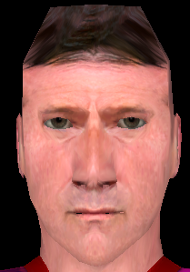
| If you worked through the HL2 Custom Character tutorial you ended up with a model with a fairly well textured head.. but no eyes! |
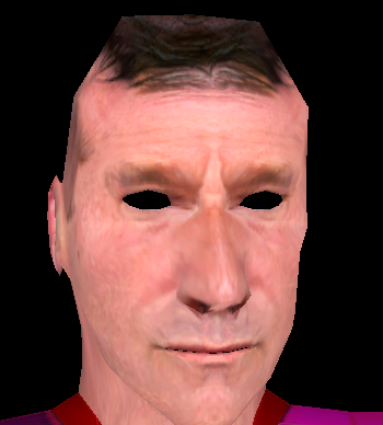 |
| In this tutorial, you'll do some work with the model and revise the model's QC file to add eyes which will follow you in a realistic fashion. |
 |
Prepare the "Position" Script |
| You'll need to determine the position of the center of the eyeball in XSI and you'll need a script to do that. You don't need to understand scripting to do it. |
| Copy the script below into a text editor (e.g., Notepad). |
|
' START SCRIPT---------------- sub info_position Dim x1,y1,z1,l_button ' Continue looping until we're done end sub |
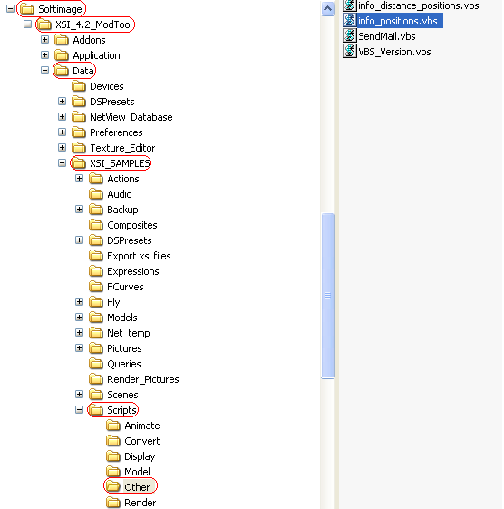
| Save the file as info_positions.vbs in the folder c:\softimage\XSI_4.2_ModTool\Data\XSI_Samples\Scripts\Other. |
 |
Positioning the Eye |
| Given the proper information, studiomdl, the SDK Source model compiler, will add working eyes to your model. You don't have to add eyes to the model itself. |
| However, you need to get that "proper information." |
| To do that, you'll position an eyeball in the model where you want it and determine it's position to pass on to studiomdl. |
| Open up XSI and load the scene file you saved at the end of the custom character modeling tutorial. |
| To make the sphere for the left eye visible, open Explorer and click the l_eye node. |
| In the main menu, click View->Hide/Unhide Selection to make the sphere for the left eye visible. |
 |
| Close Explorer. The sphere for the left eye should now be visible, selected and positioned in front of the hole for the model's left eye. |
 |
| In a Top view, select translate in the Transform panel and select Global and the z axis for translation. |
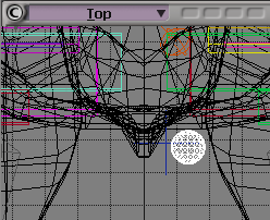
|
| Move the sphere into the model's head until it's just inside the eyelids. |
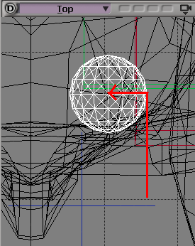 |
| Click the x axis in the translate section of the Transform panel and move the sphere a little to the left. |
| Change to a Front view. |
 |
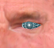
| Click the y axis in the translate section of the Transform panel and move the sphere until it's pretty well centered in the eye hole. |
| Adjust the position as you like so it appears in a natural position. |
 |
Determine the Position of the Center of the Eye |
| To determine the position of the center of the eye, you'll need to load the script you created earlier. |
| Click on the script editor icon just to the left of the Playback button in the lower left portion of the screen to open the Script Editor. |
| In the Script Editor, click File->Open.. |
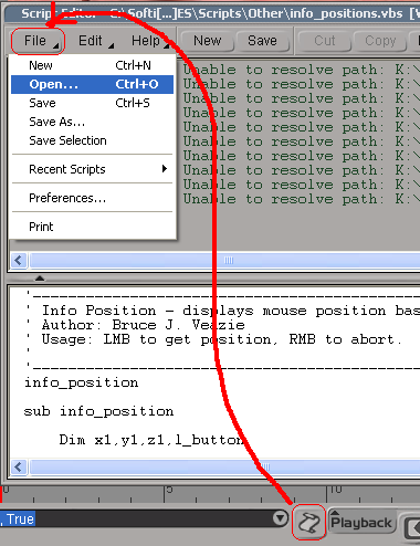 |
| Select the file info_positions.vbs you saved earlier and leave the Script Editor open. |
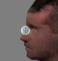
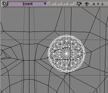
| In a Front view with a wireframe display, zoom in on the sphere. |
| In the Script Editor, click Run or, with the mouse over the Script Editor, press F5, to run the script. |
| The mouse point will change to a pen icon. Click the center of the eye sphere. |
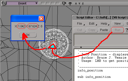 |
| Write down the X and Y values of the center of the eye. |
| Click OK to close the message box and right-click to stop the script running. |
| In a Right view with a wireframe display, run the script and click on the center of the eye sphere to get the z position. |
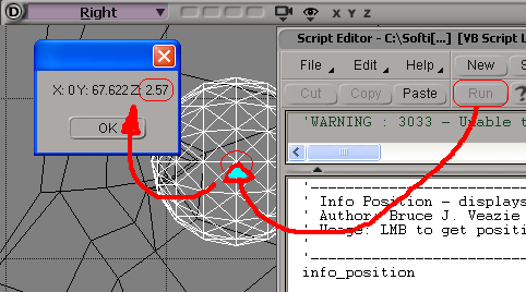 |
| Write down the z value of the center of the eye. |
| Close the message box, right-click to stop the script and close the Script Editor. You'll use the x, y and z values you've written down later when you edit the model's QC file. |
Fill in the Left Eye Hole of the Model |
| When the eyeballs appear in your compiled model, the probably won't fit the eyelids exactly. To fill in the space between the eyeball and the model's eyelids, you'll create a couple of polygon clusters to texture that will give the eye a more natural look. |
| To work with the model's eyes, you'll need to hide the eye sphere you've been working with. |
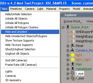
| Open Explorer, click the l_eye node. |
| In the main menu, click View->Hide and Unselect. Close the Explorer panel. |
 |
| In a User view with a wireframe display, zoom in on the hole of the left eye. |
| Use the orbit tool to position the model so you can clearly see all the vertices around the eye. |
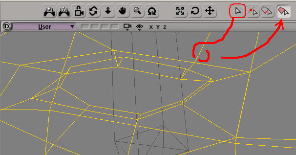
| Click the Object Select button and drag select the model. |
| Click the Polygon Select button. |
 |
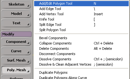
| In the Model menu, click Modify->Poly. Mesh->Add/Edit Polygon Tool, or press n. |
 |
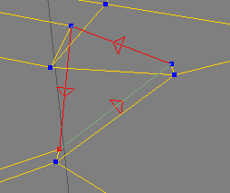
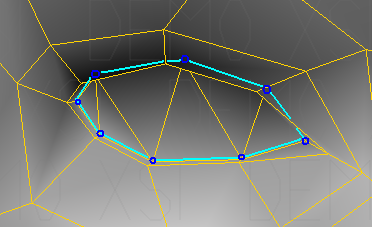
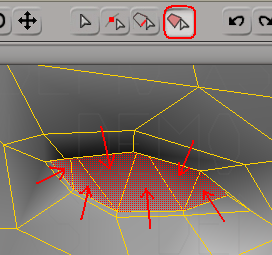
| You're going to add CCW triangles to fill the eye hole with polygons. CCW stands for "counter-clockwise." That is, you'll select vertices from the eyelid going around in a counter-clockwise direction to form new triangle polygons. |
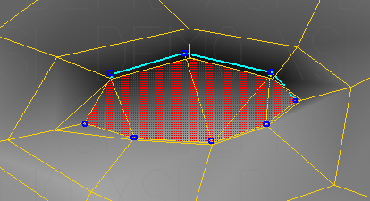 |
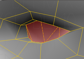
| Above is what you want for the final product. Note that vertices you want to work with are recessed from the outer parts of the eyelids. |
| The correct vertices can be difficult to select. Use the orbit and pan tools to check your work. Switch from wireframe to shaded displays to get a feeling |
| Click on the vertex at the corner of the eye and move the mouse to the next vertex to the left. |
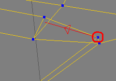 |
| Click on that vertex and move the mouse pointer to the vertex below it on the lower eyelid. |
 |
| Right-click to deselect the Add Poly tool and form the new polygon. |
 |
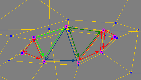
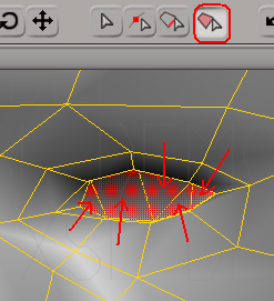
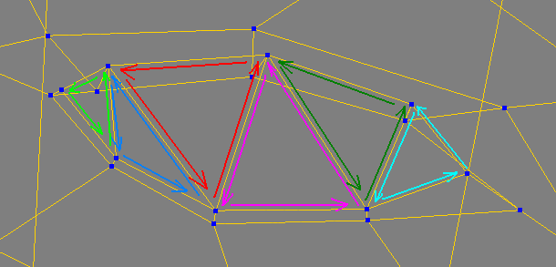
| Click the last vertex of the polygon you just created and, going CCW (counter-clockwise), make a triangle next to the first one. |
 |
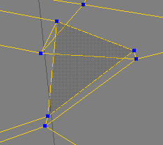
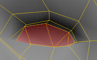
| Continue around the inside of the eyelids, forming CCW triangles as shown below. |
 |
| When done correctly, you'll end up with polygons filling the hole in the left eye. |
|
Make a Cluster for the Left Eye |
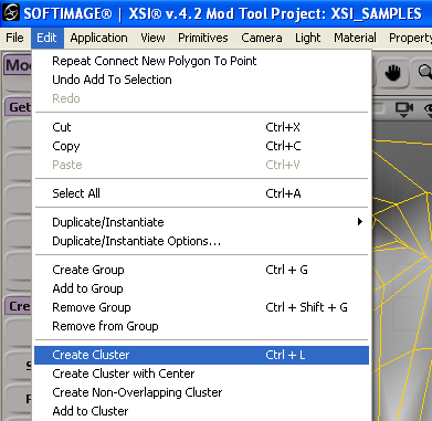
| When you filled the hole, select the Poly Select tool (if necessary) and click on polygons filling the left eye. |
 |
| In the main menu, click Edit->Create Cluster, or press ctrl-L to create a cluster of the left eye polygons. |
 |
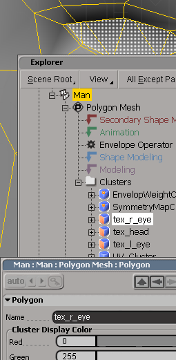
| Open Explorer and right-click on one of the operator node names. |
| Click Freeze to remove the operators from the stack. |
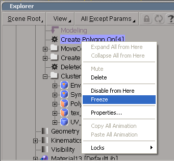 |
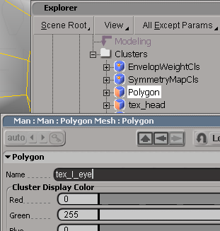
| Double-click on the Polygon cluster name and change its name in the Property Box to tex_l_eye. Close the property box and close Explorer. |
 |
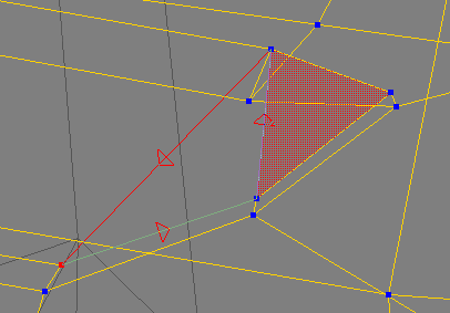
Fill in the Right Eye Hole of the Model |
| Fill in the hole at the right eye of the model in a fashion similar to the left eye. |
 |
| The vertices you want to work with are at the inner edge of the hole, just as they were for the left eye. |
| In a User view with a wireframe, zoom in to the hole in the right eye. |
 |
| Select the Add/Edit Polygon tool, or press n. |
| Form CCW triangles from the eyelid vertices as you did with the left eye. |
 |
Make a Cluster for the Right Eye |
| Select the polygons you just created for the right eye. |
 |
| Click Edit->Create Cluster, or press ctrl-L. |
| Open Explorer and rename the new cluster tex_r_eye. |
 |
| Close the property box and close Explorer but leave the tex_r_eye cluster selected. |
Adding a Texture to the Right Eye Cluster |
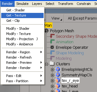
| With the tex_r_eye cluster still selected, in the main menu, click Render->Get-Texture->Image and click Yes to create a local material. |
 |
| In the Material property box, click New->New From File.. |
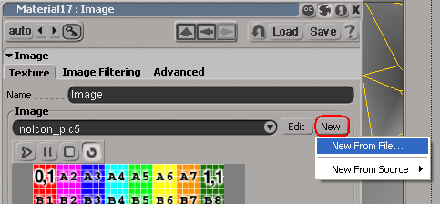 |
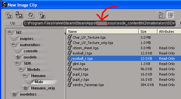
| Navigate to the sourcesdk_content\hl2\materialsrc\SDK\Models\Humans\Male folder in your Steam logon directory and select the image file eyeball_r.tga. |
 |
| Close the material dialog box. |
UV Mapping the Right Eye Cluster |
| Press alt-7 to open the Texture Editor. |
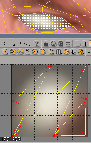
| You should be familiar with UV mapping after the last tutorial so remap the points for the right eye cluster to take up the entire texture as shown below. |
 |
| Close the Texture Editor. |
Adding a Texture to the Left Eye Cluster |
| Open Explorer and select the tex_l_eye cluster. |
| With the tex_l_eye cluster selected, in the main menu, click Render->Get-Texture->Image and click Yes to create a local material. |
| In the Material property box, click New->New From File.. |
| Navigate to the same directory as you did for the right eye texture and select eyeball_l.tga. |
| Close the material dialog box. |
UV Mapping the Left Eye Cluster |
| Press alt-7 to open the Texture Editor. |
|
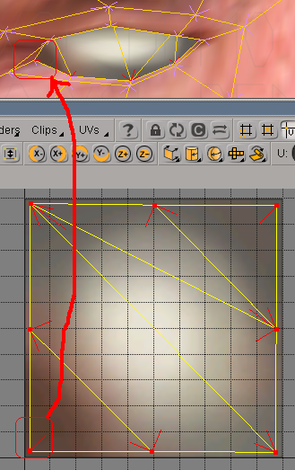
Remap the left eye cluster points to fill the entire texture. Note that the reddest portion of the texture is mapped to the inner corner of the eye. |
 |
| Close the Texture Editor. |
| Save your scene file. |
Exporting the model reference SMD file |
| In XSI, click ValveSource->Export SMD... |
| Select Model as the File Type. |
| Click the "..." button and navigate to the sourcesdk_content\hl2\modelsrc\humans_sdk\Male_sdk folder. |
| Name the file as sdk_custom_male and click OK. |
| Click OK in the SMDExport property box. |
| It may take a moment to save generate the file. Be patient. If your screen turns partially white for a moment, that's okay. |
| Close XSI. |
Revising the model's QC file to add "eyeballs" |
||
| In an ASCII text editor, open the file sdk_custom_male.qc file you created in the tutorial Creating a Custom HL2 Character Using XSI. You should find it, along with the sdk_custom_male.smd file, in the folder sourcesdk_content\hl2\modelsrc\humans_sdk\Male_sdk. | ||
| Note: | The coordinates used in XSI are rotated 90 degrees CCW about the X axis from the coordinate system used by the Source engine. The coordinates for the center of the eye in XSI ( x:1.042, y:67.624, z:2.57) translate to (x:1.042, y:-2.57, z:67.624) in the Source engine. | |
|
Edit the $attachment "eyes" line in the file as follows to set the attachment point for the eyes: //------- $attachment edit The x value is zero (0, zed) because it's the average position of the eyes. Revise the $model section of the qc file, adding two "eyeball" lines to read as follows:
|
||
|
//------- $model edit |
||
| Notice that the x coordinate for the right eye is negative (being on the opposite side of the centerline of the model from the left eye). | ||
| Notice, also, that the y and z coordinates have been swapped to reflect the orientation of the axes in the Source engine. | ||
| Save the file as sdk_custom_male.qc in the sourcesdk_content\hl2\modelsrc\humans_sdk\Male_sdk folder. | ||
| Keep the text editor open. You'll probably need to adjust the position of the eyes by editing the file. | ||
Compiling the Model and Adjusting the Eyes |
| Drag-and-drop the sdk_custom_male.qc file onto your studiomdl desktop shortcut. |
| A command prompt window will open up and studiomdl will compile the file. It may take a minute to compile. Wait for the command prompt window to close. |
| Open the Half-Life Model Viewer (HLMV) from your Source SDK launcher. |
| In the HLMV, click File->Load Model.. and naviagate to the models\sdk\Humans folder and double-click on sdk_custom_male.mdl. |
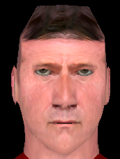 |
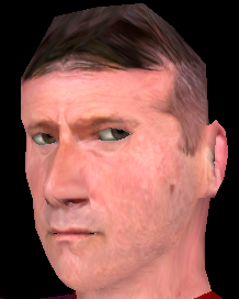
| Ideally, the eyes should look straight at you and follow you as you rotate the model. |
| As shown above, the eyes are too high in the sockets, indicating the z value of the eyeball location should be decreased. |
| If the eyes in your model appear to be too low, the z value should be increased, instead. |
| Edit the qc file and change the value 67.624 to 67.5 in both the "eyeball" lines. If you need to increase that value, change the value by a small increment to 67.7 or so. |
| Save the qc file and recompile the model by dragging-and-dropping the edited file onto your studiomdl desktop shortcut. |
| View the change in the HLMV. If you still have it open, click File->Refresh or press F5. |
 |
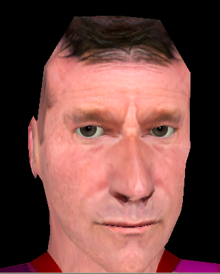
| That's more natural looking. |
| If you desire, make small adjustments in the z value in the qc file, recompile and view your model until you're satisfied. |
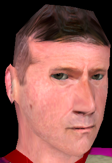
| When the vertical alignment appears to be satisfactory, rotate the model to the right and left. |
 |
| As shown above, the eyes rotate too far to the model's left side when it's rotated to its right, indicating that the y value needs to decreased. |
| Edit the qc file to change the y values to -2.71 (remember, decreasing a negative value makes it more negative). |
 |
| By playing around, adjusting the values and recompiling, I arrived at values of x: 1.042, y: -2.71, and z: 67.5 for a fairly natural movement of the eyes. |
You now have a HL2 model which you can customize. |
| By using the Male_06 model as a base for your sdk_custom_male model, it comes with all the animations that Valve has already figured out. You can add additional custom animations by following the steps in the tutorial Create a Custom Sequence for the SDK Model. |
| Things you may want to try now are: create a cluster of the upper body polygons and apply a custom shirt or tunic texture or add more polygons to the shoulders and arms for a more realistic upper body. |
| Learn more about weightmapping to make adjustments in the arm and leg vertices for more realistic movement. |
| Experiment with your custom model and have fun! |
updated 22-Sept-2005